2个稳定版本
| 1.0.1 | 2024年2月11日 |
|---|
#650 in 嵌入式开发
22KB
202 行
lcd1604_gpio
Raspberry Pi和LCD1604/LCD1602液晶显示模块通过GPIO进行接口的抽象层。
这是用于控制lcd而无需额外的I2C控制器模块
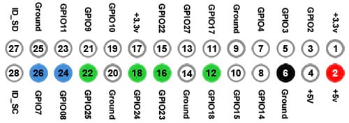
总共使用8个引脚:1 - +5v输出,1 - 地线和6 - GPIO连接
通过发送4位两次来表示单个8位字符、ASCII符号或指令/命令来完成通信
目录
请阅读说明!!!
在尝试连接之前,您必须确保您了解lcd模块和Raspberry Pi上使用的引脚,错误的接线可能会损坏您的Raspberry Pi或/和lcd模块。
首先,确保您的lcd模块与lcd1604模块具有相同的配置,其他模块可能不适用于本指南。
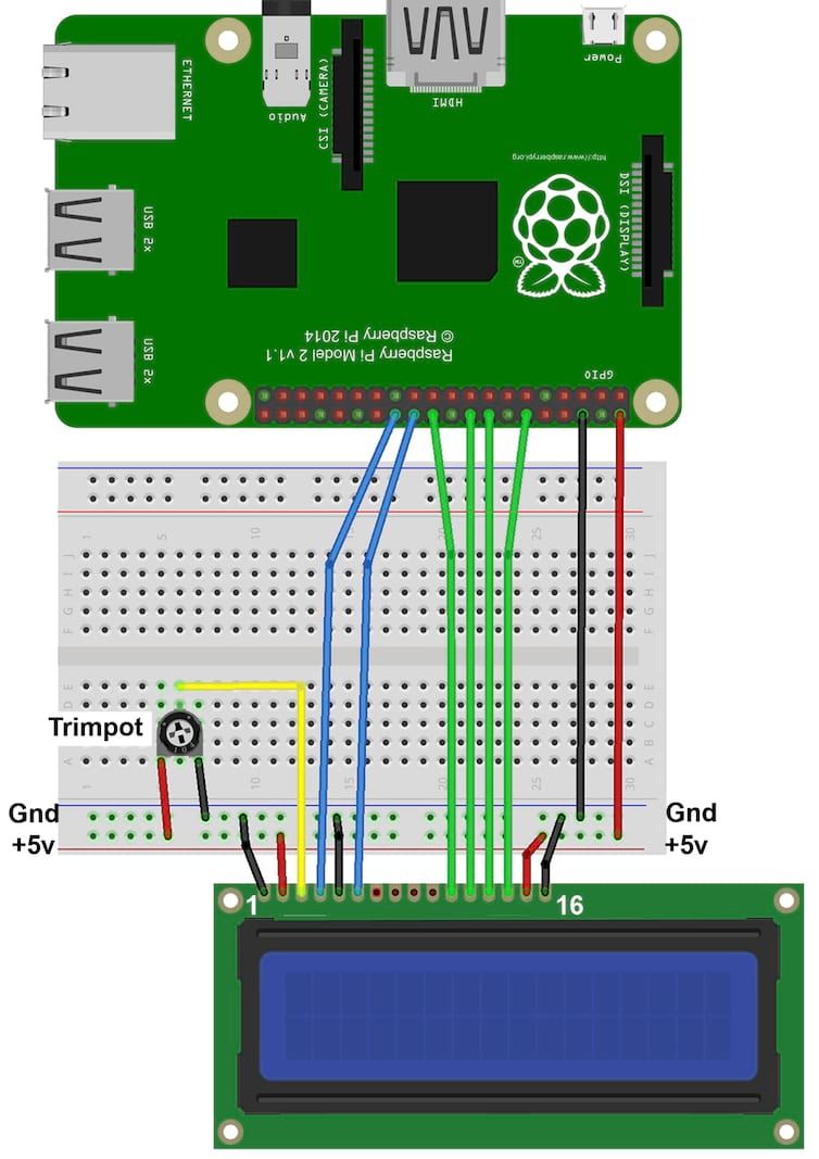
如何正确将lcd连接到pi的所有信用都归功于这篇指南 - mbtechworks.com
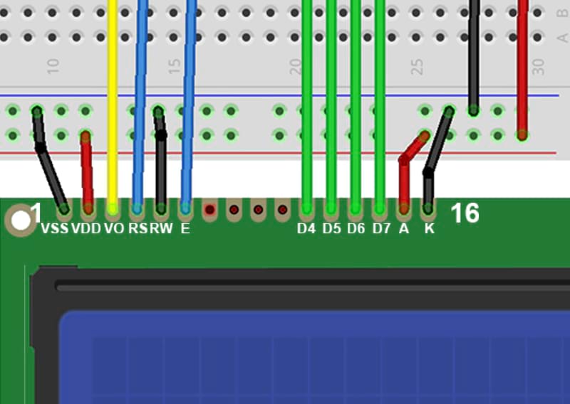
接线
| LCD引脚 | LCD功能 | 连接到 | Pi引脚 |
|---|---|---|---|
| 01 | VSS(GND) | 面包板GND | |
| 02 | VDD(+5v) | 面包板+5v | |
| 03 | VO(对比度) | 电位器的中间引脚 | |
| 04 | RS | GPIO7 | 26 |
| 05 | RW | 面包板GND | |
| 06 | E | GPIO8 | 24 |
| 07 | D0 | ||
| 08 | D1 | ||
| 09 | D2 | ||
| 10 | D3 | ||
| 11 | D4 | GPIO25 | 22 |
| 12 | D5 | GPIO24 | 18 |
| 13 | D6 | GPIO23 | 16 |
| 14 | D7 | GPIO18 | 12 |
| 15 | A(+5V) | 面包板+5v | |
| 16 | K(GND) | 面包板GND |


用法
安装
将crate添加到您的项目
cargo add lcd1604_gpio
或手动添加到Cargo.toml
[dependencies]
lcd1604_gpio = "1.0.0"
在crates.io/lcd1604_gpio上检查最新版本
基本用法
use std::error::Error;
use std::thread;
use std::time::Duration;

// Import the library
use lcd1604_gpio::{LCDController, LcdLine};

fn sleep(secs: u64) {
    let delay = Duration::new(secs, 0);
    thread::sleep(delay);
}

fn main() -> Result<(), Box<dyn Error>> {
    // Create an LCD controller instance
    // You can use the default pins specified in the README or specify your own pin configuration with LCDController::new()
    let mut controller = LCDController::default().unwrap();

    // Print LCD controller information
    println!("{controller}");

    for _ in 0..5 {
        // Display text on the LCD
        controller.display_text("Hello World!", LcdLine::Line1);
        sleep(3);

        controller.display_text("Hello Rustaceans", LcdLine::Line2);
        sleep(5);

        controller.clear_screen();
        sleep(1);
    }

    Ok(())
}
高级用法
在单独的线程中使用LCDController
基本用法示例可能不符合您的需求,因为它会锁定主线程。例如,如果您想记录一些传感器数据并在lcd显示屏上显示,那么程序将不得不等待lcd更新才能进行进一步处理。在这种情况下,您可能希望在单独的线程中使用LCDController。
use std::error::Error;
use std::sync::{mpsc, Arc, Mutex};
use std::thread;
use std::time::Duration;

use lcd1604_gpio::{LCDController, LcdLine};

enum LCDCommand {
    DisplayText(String, LcdLine),
    ClearScreen,
    Quit,
}

fn main() -> Result<(), Box<dyn Error>> {
    // Create an LCD controller instance and wrap it in a mutex
    let shared_controller = Arc::new(Mutex::new(LCDController::default()?));

    // Create a channel for communication between main thread and LCD thread
    let (lcd_tx, lcd_rx) = mpsc::channel();

    // Clone the Arc to send to the LCD thread
    let shared_controller_clone = shared_controller.clone();

    // Spawn a new thread for handling the LCD
    let lcd_thread = thread::spawn(move || {
        for command in lcd_rx {
            match command {
                LCDCommand::DisplayText(text, line) => {
                    let mut controller = shared_controller_clone.lock().unwrap();
                    controller.display_text(&text, line);
                }
                LCDCommand::ClearScreen => {
                    let mut controller = shared_controller_clone.lock().unwrap();
                    controller.clear_screen();
                }
                LCDCommand::Quit => {
                    // Cleanup and exit the thread
                    break;
                }
            }
        }
    });

    // Continue with the main thread logic here
    // ...

    // Example: Send commands to the LCD thread
    lcd_tx.send(LCDCommand::DisplayText(
        "Hello World!".to_string(),
        LcdLine::Line2,
    ))?;
    thread::sleep(Duration::new(3, 0));
    lcd_tx.send(LCDCommand::DisplayText(
        "Hello Rustaceans".to_string(),
        LcdLine::Line4,
    ))?;
    thread::sleep(Duration::new(5, 0));

    // Send a command to clear the screen
    lcd_tx.send(LCDCommand::ClearScreen)?;

    // Signal the LCD thread to quit
    lcd_tx.send(LCDCommand::Quit)?;

    // Wait for the LCD thread to finish before exiting
    lcd_thread.join().unwrap();

    Ok(())
}
常见问题(问答)
为什么我的显示显示错误的字符/符号?
这可能是由于数据引脚连接顺序错误或任何数据引脚短路造成的,使得短路的引脚同时注册为高电平,而实际上只有一个是打开的。如果出现这种情况,请使用万用表检查并重新焊接引脚。
代码
本节对于使用该框架不是必需的,但有助于理解其背后的代码工作原理。
这些是您理解树莓派和液晶屏幕之间通信所必需的所有基础知识。通过复制相同的原理,如果它支持GPIO,您可以用任何语言编写相同的模块。
引脚
基本上,数据是通过数据引脚(D4、D5、D6、D7)发送的。
RS(寄存器选择)引脚控制显示模式。
- 低电平 - 命令模式(数据被解释为命令)
- 高电平 - 字符模式(数据被解释为字符)和
RW(读/写)引脚选择显示的读或写模式
- 在这种情况下,我们将其连接到地线引脚,因为我们只会发送数据而不会读取任何内容。
E(使能)引脚在数据准备好时发送信号
4位通信
默认通信使用8位,需要连接所有8个数据引脚。在我们的场景中,我们以4位模式运行LCD显示器,通过向显示发送命令(0x32)来启用此模式。这样,我们减少了连接到树莓派的引脚数量。
通信是通过首先设置RS模式为命令或字符,然后以2-4位块发送字符或命令,并在每个块后切换E引脚来实现的,以表示数据已准备好被处理。
二进制和十六进制
首先,我们需要理解二进制如何转换为十六进制,这对于数据如何在数据引脚上发送至关重要,这将在引脚上转换为“低”为0和“高”为1。
(binary, hexadecimal, decimal)
// for the first digit of the hexadecimal
0000 0001 = 0x01 = 1
0000 0010 = 0x02 = 2
0000 0011 = 0x03 = 3
0000 0100 = 0x04 = 5
...
0000 1000 = 0x08 = 9

// for the second digit of the hexadecimal
0001 0000 = 0x10 = 16
0010 0000 = 0x20 = 32
0011 0000 = 0x30 = 48
0100 0000 = 0x40 = 64
...
1000 0000 = 0x80 = 128

// both digits
0001 0001 = 0x11 = 17
0001 0010 = 0x12 = 18
0010 0001 = 0x21 = 33
0010 0010 = 0x22 = 34
...
1001 1001 = 0x99 = 153
您可以看到十六进制的第一位表示二进制的第一4位,第二位表示第二4位
十六进制的最大值是0x99,即十进制的153,这意味着您可以用8位十六进制表示154个不同的值(因为0x00)
位运算
字符如何转换为哪些引脚信号需要激活?
字符的比较是通过逻辑AND运算符完成的,该运算符在单个位对都等于1时返回1
以字符"C"为例,它是0x43(十六进制)= 0100 0011(二进制)
"C" (0100 0011, 0x43)

// Low bits

0100 0011 = 0x43 &&
0000 0001 = 0x01
|||| ||||       == equal
0000 0001 = 0x01

0100 0011 = 0x43 &&
0000 0010 = 0x02
|||| ||||       == equal
0000 0010 = 0x02

0100 0011 = 0x43 &&
0000 0100 = 0x04
|||| ||||       != not equal
0000 0000 = 0x00

0100 0011 = 0x43 &&
0000 1000 = 0x08
|||| ||||       != not equal
0000 0000 = 0x00

// High bits

0100 0011 = 0x43 &&
0001 0000 = 0x10
|||| ||||       != not equal
0000 0000 = 0x00

...
如果操作的结果等于位==1的位对应的引脚,则将该引脚翻转至开启/高电平,表示4位(可以是高位或低位(0xHL)H-高,L-低)
参考
- 我用来解决这个问题的方法 - mbtechworks.com
- 日立HD44780液晶控制器
- GPIO引脚分配
- rppal - 框架用于通过rust与树莓派的GPIO引脚接口
- 十六进制转二进制转换器
依赖关系
~375KB